Case studies
Design of pile foundations for Kings Cross viaducts, High Speed 1, UK
 A
Repute analysis was undertaken
by
Dr Basile for
Halcrow Group Ltd (now Jacobs) to assess the
pile-foundation requirements for the viaducts of the new high-speed railway in North
London (High Speed 1, formerly known as Channel Tunnel Rail Link). These include the design of pile groups of different sizes,
subjected to a combination of vertical loads, horizontal loads and moments,
and embedded into the stiff London Clay.
A
Repute analysis was undertaken
by
Dr Basile for
Halcrow Group Ltd (now Jacobs) to assess the
pile-foundation requirements for the viaducts of the new high-speed railway in North
London (High Speed 1, formerly known as Channel Tunnel Rail Link). These include the design of pile groups of different sizes,
subjected to a combination of vertical loads, horizontal loads and moments,
and embedded into the stiff London Clay.
Results from Repute non-linear soil model demonstrate a decrease of the high axial loads at the corner piles as predicted by similar Piglet/MPILE, DEFPIG and Repute linear-elastic analyses. This decreases the design pile lengths by 1 to 2 metres (piles are generally 17m long) and results in a saving of about 400 linear metres of piles (on a total of over 300 piles). Further details on this case study may be found in Basile (2003).
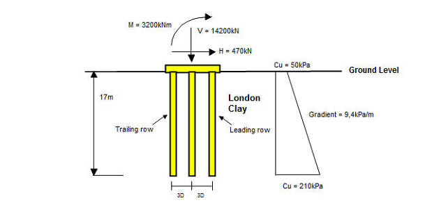
Pile design for Pier 1 is briefly presented herein as an example for the design philosophy for this project. The bored cast-in-situ reinforced concrete piles are 17m long, 0.9m in diameter, in a 3x3 layout with a centre-to-centre spacing of three pile diameters, and with the underside of the pile cap assumed at the top of the London Clay. A profile of undrained shear strength (Cu) of 50 + 9.4z kPa has been adopted, where z is the depth in m below the top of the London Clay. For the axial response, the profile of soil modulus has been derived from the correlation Es = 400Cu for the linear analyses and from Es = 1500Cu for the non-linear analysis. For the lateral response, the profile of soil modulus has been assumed to increase linearly with depth from a value of zero at the top of the London Clay at a rate of 4.14MPa/m for the linear analyses and 6.15MPa/m for the non-linear analysis. The applied vertical loads (V) result from the combined effect of live and dead loads, whereas the horizontal loads (H) and moments (M) are mainly generated by the high-speed trains braking and accelerating. The loads acting on the cap have been estimated as V = 14200kN, H = 470kN and M = 3200kNm.
This problem has been analysed using the computer programs MPILE, DEFPIG and Repute (using linear and non-linear soil models), and the main results are given in the table below. In the linear elastic range, there is a reasonably good agreement between the group deformations and axial load distribution predicted by the different codes. However, it is worth noting the differences in the predicted pile head lateral loads and bending moments. These are due to the interaction between the axial and lateral responses of the piles, resulting in higher loads for piles in the leading row than for piles in the trailing row of the group. While this load-deformation coupling effect is modelled by the Repute analysis, MPILE and DEFPIG disregard this interaction and therefore predict the same lateral loads and bending moments for both the leading and trailing rows of the group. This results in a significant underestimate of the maximum values of lateral load and bending moment and may therefore lead to an unsafe design of the piles.
Finally, it is worth noting that the use of Repute non-linear soil model leads to lower group deformations (due to the higher value of soil modulus adopted) and a decrease of predicted loads on the most heavily loaded row of piles (i.e. the leading row), thereby resulting in a more uniform and economical load distribution between the piles.
| MPILE | DEFPIG | Repute (linear) | Repute (non-linear) | |
| Group centre settlement (mm) | 9.0 | 11.3 | 11.6 | 4.0 |
| Group deflection (mm) | 3.2 | 4.3 | 3.9 | 2.7 |
| Axial load at top of corner piles of leading row (kN) | 2220 | 2210 | 2230 | 2100 |
| Axial load at top of corner piles of trailing row (kN) | 1700 | 1670 | 1640 | 1520 |
| Lateral load at top of corner piles of leading row (kN) | 66 | 62 | 94 | 76 |
| Lateral load at top of corner piles of traling row (kN) | 66 | 62 | 23 | 35 |
| Bending moment at top of corner piles of leading row (kN) | 120 | 177 | 225 | 179 |
| Bending moment at top of corner piles of trailing row (kN) | 120 | 177 | 87 | 124 |
Acknowledgments
Appreciation is expressed to Halcrow Group Ltd for permission to publish the above results.
References
Basile, F. (2003). Analysis and design of pile groups. In Numerical Analysis and Modelling in Geomechanics (ed. J. W. Bull), Spon press, London, Chapter 10, pp 278-315.
about us
consulting
software